October 30, 2011

The Double Transverse Foramen

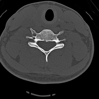
The double transverse foramen in the cervical spine is a normal variant that, according to the literature, occurs most often in the C6 vertebra transverse process, with decreasing frequency above and below.  It is claimed that the vertebral artery splits at these accessory foramen (which are always smaller), and rejoins distally, although this is controversial, and it is not entirely clear from the literature whether the accessory foramen usually contains artery, vein, nerve, neither, or some combination. 

Bilateral transverse foramina incidentally noted at C5 on this trauma patient.
Bilateral transverse foramina also incidentally noted at C6 on this trauma patient.  C6 is the most common level to find double transverse foramina.

One source claims that accessory foramina occur in 1.6% of observed cervical spines. The duplication is thought to represent the failure of controlled regression of two intersegmental arteries and a segment of the primitive dorsal aorta.  An extremely rare triple transverse foramen has been reported.


1. Francis CC. "Dimensions of the cervical vertebrae" The Anatomical Record. Anat. Rec. Vol 122: 4 pp.  1097-0185
2. Wysocki J, Bubrowski M, Reymond J, Kwiatkowski J. "Anatomical variants of the cervical vertebrae
and the first thoracic vertebra in man" Folia Morphol. Vol. 62, No. 4, pp. 357–363
3. Murlimanju BV, et al. "Accessory Transverse Foramina in the Cervical Spine: Incidence, Embryological Basis, Morphology and Surgical Importance" Turkish Neurosurgery 2011, Vol: 21, No: 3, 384-387

October 22, 2011

Luckenschadel

Lucke (gap) + schadel (skull)

The luckenschadel (sometimes called "luckenschadel skull," although this is technically redundant) is a calvarial abnormality most often associated with a Chiari II malformation and a meningomyelocele

The luckenschadel is an ossification disorder which leads to multiple deep pits in the membranous bones of the newborn skull (favoring the parietal and occipital bones).  It has a classic radiographic "honeycomb" appearance (below), which is diagnostic. 

Alternating regions of cortical fenestration, creating a "honeycomb" appearance, compatible with Luckenschadel.  There is also scalp swelling.  Vaginal delivery of these infants can be problematic since cranial pressure on a fenestrated skull can lead to intracranial hemorrhage.
3D CT reformats of luckenschadel

The grooves in the skull do not necessary traverse the entire bone, and when limited to the inner table, they are called "craniolacunae."  If palpable and involving both the inner and outer table, they are then referred to as "craniofenestrae."  The "waviness" of the skull outline on axial imaging is detectable on obstetric ultrasound (below).


Developmentally, luckenschadel is similar to myelomeningocele, in that there is failure of normal bone formation over the brain.  Some sources claim that it develops in part due to lack of normal cerebral ventricular distention due to an open neural tube defect in the Chiari II malformation.  Over the first 6 months, the fenestrae fill in, and luckenschadel is a diagnosis that can only be made in neonates.


1.   Vigliani, M.  "The luckenschadel skull: a forgotten entity"  Obstetrics and Gynecology: Volume 111(2, Part 2), February 2008, pp 562-565
2.  Coley BD. "Ultrasound diagnosis of luckenschadel (lacunar skull)" Pediatric Radiology, Volume 30:2. pp 82-84.

October 17, 2011

The "Two-eyed Scotty Dog"


The vertebral transverse process contains two additional processes of its own.  The more superior (and larger) of the two is called the mammillary process, which connects posteriorly to the superior articular facet, and is in the same plane as the transverse process.


There is normal variation in the size of this process, but occasionally, a large mammillary process in a sufficiently obliqued radiograph will give the appearance of the "two-eyed scotty dog," with one eye being the usual pedicle and the other eye being the mammillary process.

Oblique view showing the "two-eyed Scotty dog" appearance at L3.  The anterior ring-shaped opacity represent the pedicle (large arrow); the more posterior ring-shaped opacity represents a prominent mammillary process (small arrow).

1.  Patel NP, Kumar R, Kinkhabwala M, Wengrover S. "Radiology of lumbar vertebral pedicles: variants, anomalies, and pathologic conditions"  Radiographics. Vol 7:1 (Jan 1987) pp. 101-137.

October 15, 2011

Torus Torus Torus

50Y M with 60 pack-year history of smoking presents with a painless lump on the hard palate.  Appropriate history taking determines that it has been slowly developing over a long period of time, and the finding can be dismissed as a
torus palatinus, a normal variant.
There are three tori that can potentially occur in the skull: the torus palatinus, the torus maxillaris, and the torus mandibularis.  All three are relatively common (autosomal dominant with variable penetrance) but virtually uneventful bony exostoses.  Case reports of symptomatic tori exist in the literature, but the value of recognizing them on a CT of the skull is essentially to dismiss them as a normal variant.


1.  Gorsky M, Bukai A, Shoha M. "Genetic Influence on the Prevalence of Torus Palatinus" American Journal of Medical Genetics 75:138–140 (1998)
2. Tran KT, Shannon M. "Images in Clincal Medicine: Torus Palatinus"  NEJM 356;17 www.nejm.org april 26, 2007

October 14, 2011

Modic Type 1 change and low back pain

Although controversial, the Modic classification of vertebral endplate changes remains a handy short cut to describe degenerative signal abnormalities.  Originally, two classes were described, the creatively entitled Modic type 1 change and Modic type 2 change.  A rare third Modic type 3 change was added later.  Today's post will focus on the first class: Modic type 1 changes.


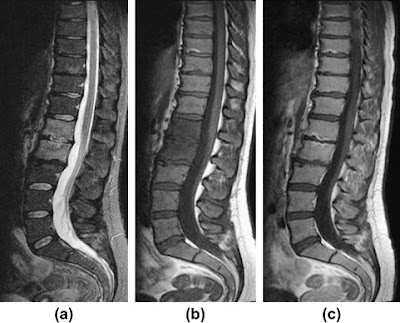
Type 1 changes are T1 hypointense and T2 hyperintense.  Like most other areas in the body that exhibit this signal pattern, it is a reflection of increased fluid content in the endplate... signifying bone marrow edema and inflammation.  Type 1 changes exist in a spectrum from Type 1 --> Type 2, indicating an evolution of the degenerative process.  Type 2 can then become active again: Type 2 --> type 1.  If caught at a transition point, the changes are a mixed type 1/2.

T1 sagittal image of the lumbar spine demonstrates a band of decreased signal at the superior  L3 endplate and inferior L2 endplate... the decreased signal is an indication of edema.

T2 sagittal image of the lumbar spine in the same patient demonstrates the same band of endplate signal change, but with increased signal compared to the  T1-weighted images.  The brighter T2 signal is consistent with fluid/edema.

Histologic examination of the endplates in Modic type 1 change show fissuring of the endplates and formation of fibrovascular granulation tissue.  Current opinion is that this change is a result of disc degeneration rather than a factor contributing to disc damage.

The diagnostic dilemma concerning Modic Type 1 changes is that an infectious process (i.e. a discitis) has a similar pattern in the vertebral bodies with inflammation and edema at both endplates adjacent to an infected disc.  The deciding factor is the appearance of the disc itself.  Discitis presents with increased T2 signal intensity, whereas a degenerated, dessicated disc presents with normal or hypointense signal on T2-weighted sequences.  Also, in an infection, other signs are likely to be present, such as erosion of the endplates, a paravertebral soft tissue mass, and appropriate lab tests (CRP (100% sensitive) and ESR).

28Y F with  LBP and fever.  Sagittal T2 FS, Sagittal T1 and Sagittal T1+C show L1-L2 discitis and vertebral osteomyelitis.  Note the similar T1 & T2 pattern with Modic type 1 changes.  The difference lies in the disc changes, endplate erosions, and appropriate patient history.

Current opinion also believes that Modic type 1 changes represent a more active form of degenerative change and increased inflammatory cytokines have been recovered from Type 1 vertebral bone.  This Modic type is believed by some to be most closely related to lower back pain, but this remains controversial and studies have been limited by small sample sizes.


1. Rahme R, Moussa R. "The Modic Vertebral Endplate and Marrow Changes: Pathologic significance and Relation to Low Back Pain and Segmental Instability of the Lumbar Spine." AJNR 29 (May 2008)  pp. 838-842.
2. Dunbar JAT, Sandoe AS, et al. "The MRI appearances of early vertebral osteomyelitis and discitis," Clinical Radiology, Volume 65, Issue 12, December 2010, Pages 974-981,

October 13, 2011

Eagle syndrome

The slender styloid process (Gk. stylus = pillar, instrument for writing (incidentally the root of the word "style")) is seldom seen on most cadaveric skulls since it frequently snaps during dissection.  Technically part of the temporal bone (a.k.a. the "temporal stylus"), the styloid is a point of attachment for multiple small muscles... basically any muscle that originates with the prefix "stylo-" (stylohyoid m., styloglossus m., stylopharyngeal m.).  Just posterior to the styloid process is the stylomastoid foramen, which transmits the exiting CN VII and a small stylomastoid artery.

The skull base ala CT axial views.  The temporal styloid process is circled in red.

Fractures of the styloid have been reported as case reports, but the main contribution of the styloid process to pathology is through Eagle's syndrome in which an elongated styloid process, or a calcified stylohyoid ligament causes chronic neck pain or globus sensation.  The styloid normally measures somewhere around 2-3 cm and in the proper setting, an elongated styloid may contribute to localized pain.  Eagle syndrome can occur unilaterally or bilaterally and cause a variety of nonspecific symptoms including dysphagia, headache, pain on rotation of the neck, pain on extension of the tongue, or dysphonia.  Below is a lateral radiograph of Eagle's syndrome demonstrating a heavily ossified stylohyoid ligament, and beneath that, axial CT images of the same patient.

Heavily calcified structure extending from the skull base to the hyoid is compatible with a stylohyoid ligament calcification (Eagle Syndrome)


Axial CT images of the patient above demonstrate an ossified left stylohyoid ligament.  Compression and entrapment of adjacent structures is not too difficult to imagine with a ossified ligament this flagrant.


One source believes the ultimate source of pathology due to the elongation is entrapment of the glossopharyngeal (CN IX) nerve.


1. Prasad KC, Kamath MP, et al.  "Elongated Styloid Process (Eagle's Syndrome): A clinical study" Journal of Oral and Maxillofacial surgery. 60:2 (Feb 2002) pp. 171-175.
2. Murtagh RD, Caracciolo JT, Fernandez G. "CT Findings associated with Eagle's Syndrome" AJNR Am J Neuroradiol 22:1401–1402, August 2001
3. Slavin KV. "Eagle syndrome: entrapment of the glossopharyngeal nerve? Case report and review of the literature J Neurosurg 97:216–218, 2002

October 5, 2011

The "Human Tail"

Only thirty-three human tails have been reported in the literature, and there is some question how many (if not all) of these represent "pseudotails."  The difference?  A "true" human tail would consist of adipose tissue, skeletal muscle, blood vessels and nerves (no human tail has ever been described containing vertebral bone).  A "pseudotail" is merely a tissue collection (usually a lipoma, teratoma, or myelomeningocele) pouching out at the coccyx with the appearance of a tail (as in the case below).


Human "tails" have been noted to develop in the fetus and then regress.  Case reports note that if the tail persists in the newborn, the finding is very frequently associated with other spinal variations or abnormalities.  Although a tail is certainly not very difficult to detect on a newborn, the history should prompt a careful search of the spine for other spinal abnormalities.

1. Dubrow TJ, Wakym PA, Lesavoy MA. "Detailing the Human Tail" Annals of Plastic Surgery. 20:4 (1988)
2. Alashari M, Torakawa J. "True Tail in a Newborn"  Pediatric Dermatology 12:3 263-266 (1995)

October 4, 2011

Paraspinal Musculature: The Perils of Cricket

Attaching inferiorly to the fibers of the iliolumbar ligament, superiorly to the lowest rib, and medially to the transverse processes of the L1-L4 vertebral bodies, the quadratus lumborum muscle is visible in virtually all MRI studies of the lumbar spine... at least the axial sequences.  The QL is also visible in virtually every abdominal/pelvis CT, too.


Since the anterior surface of the muscle forms the front of the thoracolumbar fascia, it remains relatively sequestered from abdominal processes that affect its anterior neighbors: the kidney and psoas muscle.


Most of the interest in the world today in the quadratus lumborum muscle comes from Australia, where there is concern that fast-bowl cricket is leading to injury of the L4 pars interarticularis injury (an injury also commonly seen in tennis players).  Radiologists there determined that an enlarged quadratus lumborum is associated with an ipsilateral L4 pars fracture, however, there is debate whether the asymmetry of the muscle is a source of stress on the vertebral body or may be just a defensive adapatation to stress on the vertebral body.

Incidentally, the QL is the muscle that allows to hold our body horizontally on one elbow (as below).


1. McGill S, Juker D, Kropf P. "Quantitative intramuscular myoelectric activity of quadratus lumborum during a wide variety of tasks" Clinical Biomechanics 11:3, 170-172 (April 2011).
2. Engstrom, C. M., Walker, D., Kippers, V. and Buckley, R.  "Quadratus lumborum asymmetry and pars interatricularis injury in cricket fast bowlers: A prospective MRI examination" (2000). Quadratus lumborum asymmetry and pars interatricularis injury in cricket fast bowlers: A prospective MRI examination. In: , 2000 Pre-Olympic Congress Book of Abstracts. International Congress on Sport Science, Sports Medicine and Physical Education, Brisbane, (191-192). 7-12 September 2000. 

October 3, 2011

Lumbosacral transitional vertebrae

The Castellvi system for organizing lumbosacral variations.
Useful only for classification, not prognostic significance.
The design of the spine is awkard enough as it is, with the majority of the body's weight being transferred through L5-S1, but as if to make an awkward system even a little more awkward, every so often congenital vertebral variations occur at the lumbosacral junction and confuses the typical layout (see Hox genes in the 9/29/2011 post).

There are two main possibilities for a lumbosacral transitional vertebrae:

- "lumbarization of S1"
- "sacralization of L5"

which seem to be two ways of looking at the same thing... except in the first situation you essentially end up with an extra lumbar vertebra ("L6"), and in the second, you end up with one too few lumbar vertebrae (L1-L4).  Note that, unlike the "gorilla bone" example from 9/29/2011, it's assumed that there are the normal 12 ribs in both these situations, but then again it's more common to have thoracolumbar variations if there is a lumbosacral variation...

... so the final result of all this madness is that the only absolutely sure way to know which variations you're dealing with in the spine is to count down from C2...

...and numbering of these segments is critical since they frequently get intervened upon, either by surgery or by anesthesia.


A recent study demonstrated that the iliolumbar ligament (described as "absent in 70%" in earlier studies), actually denotes the lowest lumbar vertebra, which is not always L5 and should not be used as a marker for L5. 

Some object to the use of "L6" as the best term for this lowest lumbarized S1 vertebra since there is no L6 nerve root.  If "L6" is used, then the S1 nerve root would pass out beneath it, and then the S2 nerve root would passes out below/through the S1 neuroforamina...... and the whole vertebra-nerve root thing goes cattywhompus.

It is claimed by some, however, that the L5 nerve root always passes out the "last mobile" segment of the spine, so in a patient with a lumbarized S1 like the one below, the last mobile level is L6-S2, and the functional L5 nerve root corresponds to the "L6" nerve root.  The point hold true for patients with a sacralized L5 as well, and the L4 nerve root serves the usual function of the L5 nerve root.  This point has been debated, and some feel that this nerve root also shares some aspects of S1... but as of today, no thorough study has determined which is correct (perhaps both).


One other side note: whether lumbosacral transitional vertebrae is related to low back pain is controversial. A recent study demonstrated that nearly a 1/3 of a normal population sample had at least minor changes of transitional lumbosacral vertebrae in the spine, implying that it may not be as closely associated with low back pain as was once thought. Another recent study positively correlated Castellvi types II and IV with an increase in low back pain.

---
1.  Apazidis A, Ricart P, et al. "The Prevalence of Transitional Vertebrae in the Lumbar Spine."  The Spine Journal 11 (2011) 858-862
2. Kim YH, Lee PB, et al. "Dermatome Variation of Lumbosacral Nerve Roots in Patients with Transitional Lumbosacral Vertebrae" Anesthesia & Analgesia 2008; 106:1279-83
3. Carrino JA, Campbell PD, et al.  "Effect of Spinal Segment Variants on Numbering Vertebral Levels at Lumbar MR Imaging"  Radiology, 259, 196-202 April 2011
4. Nardo L, Alizai H, Virayavanich W. "Lumbosacral Transitional Vertebrae: Association with Low Back Pain" November 2012 Radiology,265, 497-503.

October 2, 2011

The Pit and the Pyramid

The middle ear has more nooks and crannies than a gnome's cave (gnomes live in caves, right?), and these are places where all kind of nastiness can hide out.  One example of such a hiding place is the sinus tympani, tucked up in the superior, posterior, and medial wall of the middle ear behind the pyramidal eminence.  The importance of the sinus tympani for radiologists is because this little nook is not always well visualized by ENT endoscopy, and it's a little cranny where acquired cholestomas, specifically the pars tensa cholestetomas, like to originate.

Hi res axial CT of the IAC

Hi res coronal CT of the IAC

There is variation in the depth of the sinus tympani from nearly flat with virtually no sinus at all, to a deep, hidden pocket... which of course is the more dangerous end of the spectrum.  The images below show how the sinus tympani is not always completely visualized during endoscopy.

In these endoscopic views, the sinus tympani (st) is not completely visualized.  Note also the pyramidal eminence (pe) and the stapedius muscle tendon (ts) exiting to attach to the stapes (s).

So why is the pyramidal eminence blocking the view? It's because it wraps around the tiny stapedius muscle (the smallest skeletal muscle in the human body). The stapedius, not surprisingly, attaches to the stapes bone, where it dampens vibrations in the stapes and decreases the volume of incoming sound.  Since it is innervated by a tiny branch from the nearby CN VII, pathologies affecting this cranial nerve (such as Bell's palsy) can result in a loss of sound dampening or hyperacusis.  Below is a schematic of the middle ear (in a non-radiologic orientation) which demonstrates the relationship of the sinus tympani, pyramidal eminence (unmarked) with its stapedius muscle exiting, and the stapes.


1. Abdel Baki F, Badr El Dine M, et al. "Sinus Tympani Endoscopic Anatomy" Otolaryngology - Head and Nexk Surgery  127: 3 158-162 (Sep 2002)
2. Tomura N, Sashi R, et al. "Noraml Variation of the Temporal Bone on High-Resolution CT: Their Incidence and Clinical Significance."  Clinical Radiology 50, 144-148 (1995)
3. Marchioni D, Alicandri-Ciufelli M, et al. "Pyramidal eminence and subpyramidal space: an endoscopic anatomical study"  Laryngoscope. 2010 Mar;120(3):557-64.

October 1, 2011

The Gouty Spine

 Gout is classically a disease of the appendicular skeleton with characteristic radiologic features (sclerotic, well-marginated erosions with overhanging edges), diagnostic joint aspiration findings (needle-shaped negatively birefringent monosodium urate crystals), and typical serum abnormalities (hyperuricemia).  Gout also tends to strike characteristic locations, especially the well-recognized site at the first metatarsophalangeal joint ("podagra")


But despite its characteristic findings and locations, the relatively high prevalence of gout leads to a number of atypical presentations, including gout located in the discs and facet joints of the spine.  The majority of spinal involvement in gout occurs in patients who already carry a known diagnosis, so it's not too challenging to put it on the differential for acute back pain...
... what can be challenging is using imaging to determine whether findings in the spine in a patient with a history of gout are related to an unusual site of gouty attack, or whether they are related to a concurrent, much more common process (e.g. osteomyelitis or epidural abscess).

Radiographic and CT imaging can show vertebral endplate erosion, disc space narrowing, and a soft tissue mass (tophus), but these findings lack specificity, and, although gouty involvement of the spine is rare, tophi have been mistaken for tumor or abscess in the past.  The axial CT image below comes from a 27Y M with a 6 month history of low back pain and a four year history of hyperuricemia, and demonstrates hyperdense periarticular deposits with diffuse stippled calcifications and juxta-articular bony erosions around the facet joints.


MRI adds more specificity to the findings, and adds information related to potential spinal cord or nerve root compression, but it still lacks specificity... especially since a tophus can show quite variable presentations.  The sagittal T1, T2, and postcontrast T1 images below come from the same 27Y M patient as above:

T2WI: Heterogeneous signal within the tophus
T1WI: Heterogeneous low signal in the tophus
Postcontrast T1WI: Variable enhancement within the tophus
Given the variability in MRI presentation, this modality seems most useful to decide against other masses with more characteristic presentations, and to assess neurologic impingement.

A new and elegant method of diagnosis of spinal gout involves the use of dual-energy CT scanningSince calcium and urate demonstrate different attenuation characteristics at different kVp values, urate deposition can be isolated and color coded as in the example below.


 This image on the right is the color-coded dual energy CT image showing urate crystal deposition in the facet joints (green) of an 82Y man with worsening back pain.  Not surprisingly, he had not been receiving relief from multiple steroid injections for his advanced degenerative disease.

Of note, reports of gouty involvement of the spine range from the cervical spine to the lumbar spine and sacroiliac joints, and there appears to be no preferential spinal location.


1. Staub-Schmidt T, Chaouat A, et al. "Spinal Involvement in Gout" Arthritis & Rheumatism 38:1, 1529-0131
2. King JC, Nicholas C. "Gouty arthropathy of the lumbar spine: a case report and review of the
literature" Spine (Oct 1997) 1;22(19):2309-12.
3. Hsu CY, Shih TT. "Tophaceous gout of the spine: MR imaging features" Clin Radiol. 2002 Oct;57(10):919-25.
4. Madhura D, Peterson J,et al. "Clinical Utility of Dual-Energy CT for Evaluation of Tophaceous Gout" Radiographics September-October 2011 31:1365-1375